Single-sided photonics alignment system consisting of H-811 hexapod and NanoCube® nanopositioner; E-713 digital controller with 4 analog inputs; C-887 hexapod controller with 2 analog inputs; firmware routines for high-speed alignment tasks; software package
F-713.Hxx Compact, High-Speed 6-DoF Photonics Alignment Systems
Single-Sided and Double-Sided, Upright and Low-Profile, Fully Automated Array Alignment Routines
- Integrated scan/align routines for SiPh wafers, photonic devices, PICs, and fiber optics
- Powerful array alignment algorithms
- Fast, simultaneous optimization across multiple devices, I/Os, and degrees of freedom (DOF)
- Broad and deep software support for rapid process development, including support for popular languages such as C#, Python, LabVIEW, and MATLAB on Windows and Linux
- Automatic alignment in typically <0.5 s
- Responsive application and product support from PI worldwide


Problem solved
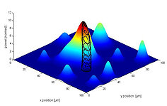
PI's Fast Multichannel Photonics Alignment (FMPA) solutions combine application-optimized, fab-ready, highly dynamic alignment stages with sophisticated controllers that integrate the world's most advanced and effective first-light search, profile, and power optimization alignment algorithms.
Reduction of alignment time by 99%
This award-winning technology addresses the number one cost driver for photonics test and assembly: the precise alignment required for each element and channel. Legacy alignment technologies date back to the 1980s and can take minutes to complete. PI's fast optical alignment solutions reduce the time required by typically 99%, routinely completing the task in less than one second. Studies show that up to 80% of the cost of a photonic device is attributable to alignment, without FMPA. If this 80% share of costs is reduced by 99%, the benefits to the manufacturing industry are obvious. And with projections of three orders of magnitude escalation in demand for photonic components in the near future, as new applications and devices emerge, FMPA is a true enabler.
Versatile, compact, proven solutions for 6-DoF alignment challenges
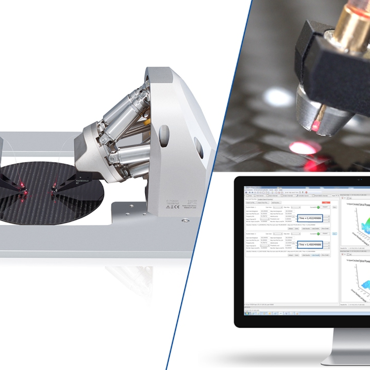
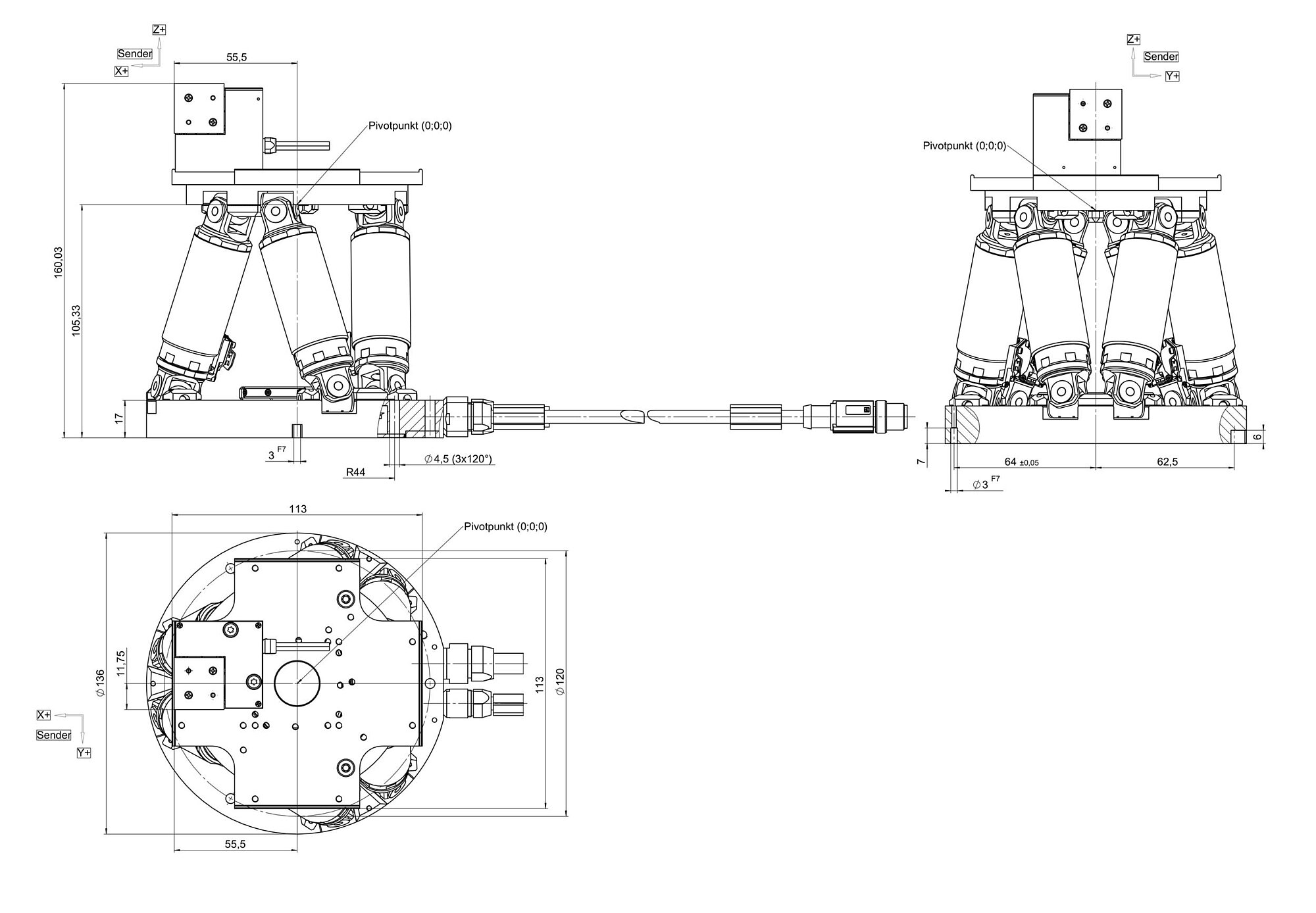
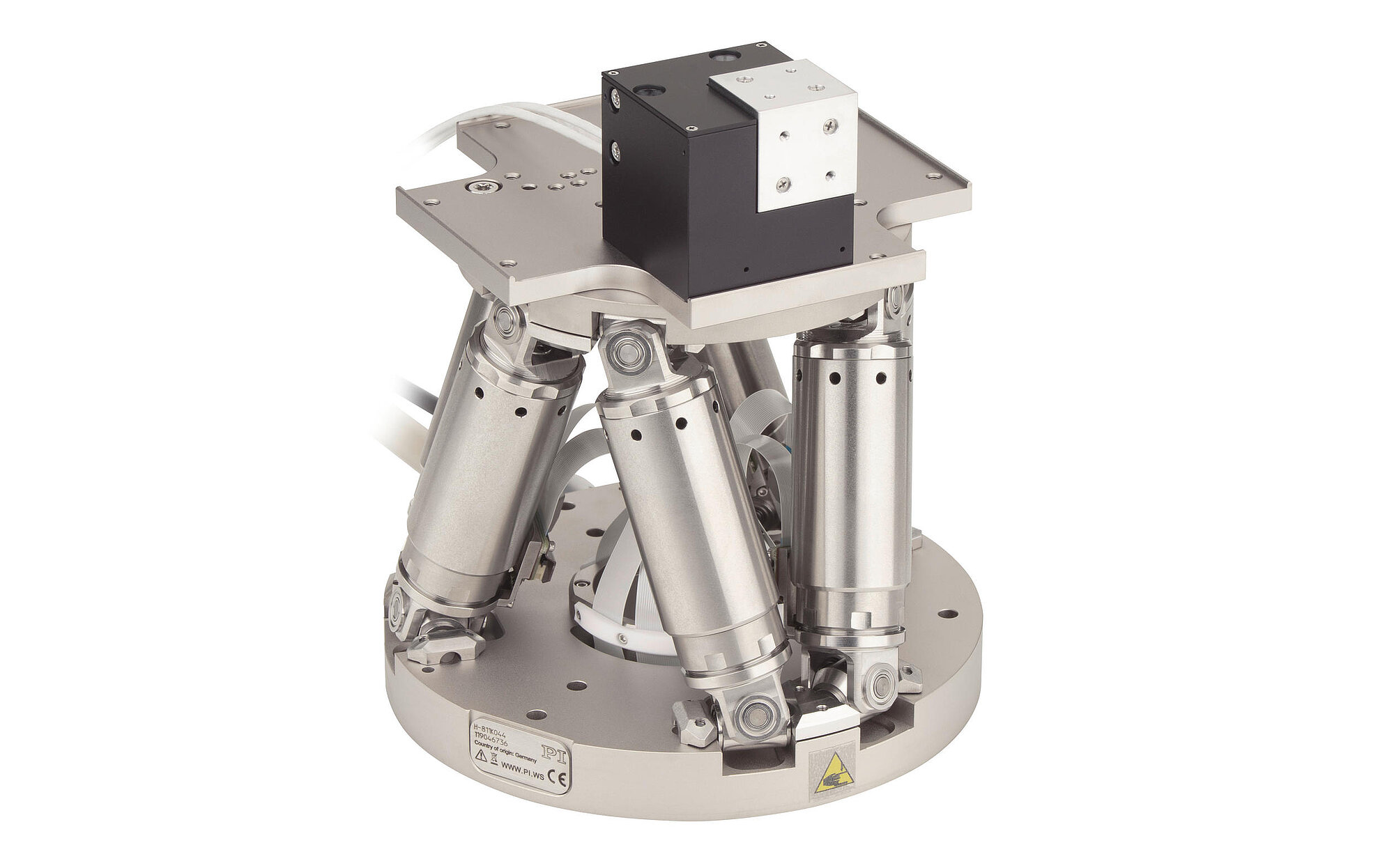
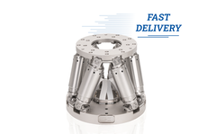
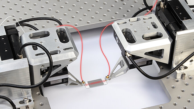
These integrated solutions combine PI's premier compact hexapod with a highly dynamic, ultra-resolution NanoCube® fast piezo scanning stage to provide 6-DOF positioning, scanning, and optimization. Since their introduction in 2016, these unique microrobotic solutions have enabled a variety of applications ranging from silicon photonics wafer probing to array alignment and automated photonics device assembly. They are the solution of choice for many leading OEMs and in-house integration teams. The applications are complex, but the reasons for the choice are simple: groundbreaking alignment speed that improves production throughput by two orders of magnitude, an easy-to-master command set complemented by broad and deep software support, and global application expertise and support.
Synergies for higher performance
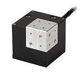
The combined hexapod and NanoCube® mechanisms operate synergistically to enable simultaneous optimization across multiple channels, I/Os, and DoF, with parallel optimization across all DoF and I/Os. For example, the NanoCube® offers extreme speed and long life through flexure guides and PICMA piezo drives, while the hexapod offers generous travel that includes pitch-yaw-roll positioning and alignment optimization important for arrayed waveguides, etc. High-resolution analog inputs provide connectivity to power measurement devices, such as PI’s F-712.PM1 high-bandwidth optical power meter, for optimization and profiling, enabling efficient and fast automated fiber optical alignment. Soft limits are supported to ensure process safety.
Low profi le and upright configurations
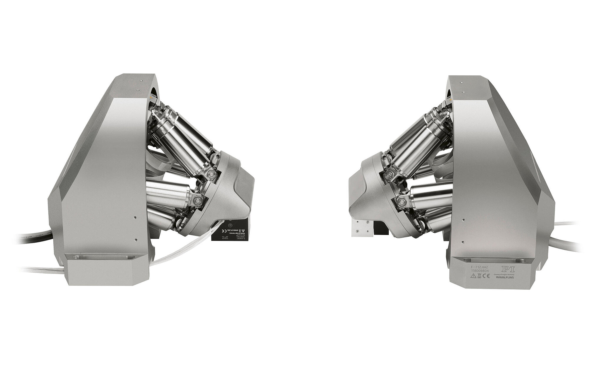
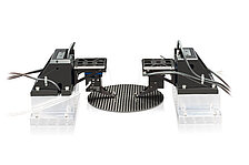
PI’s 6-DoF fiber alignment systems include the F-713.HA1, F-713.HA2, and F-713.HU1 standard configurations.
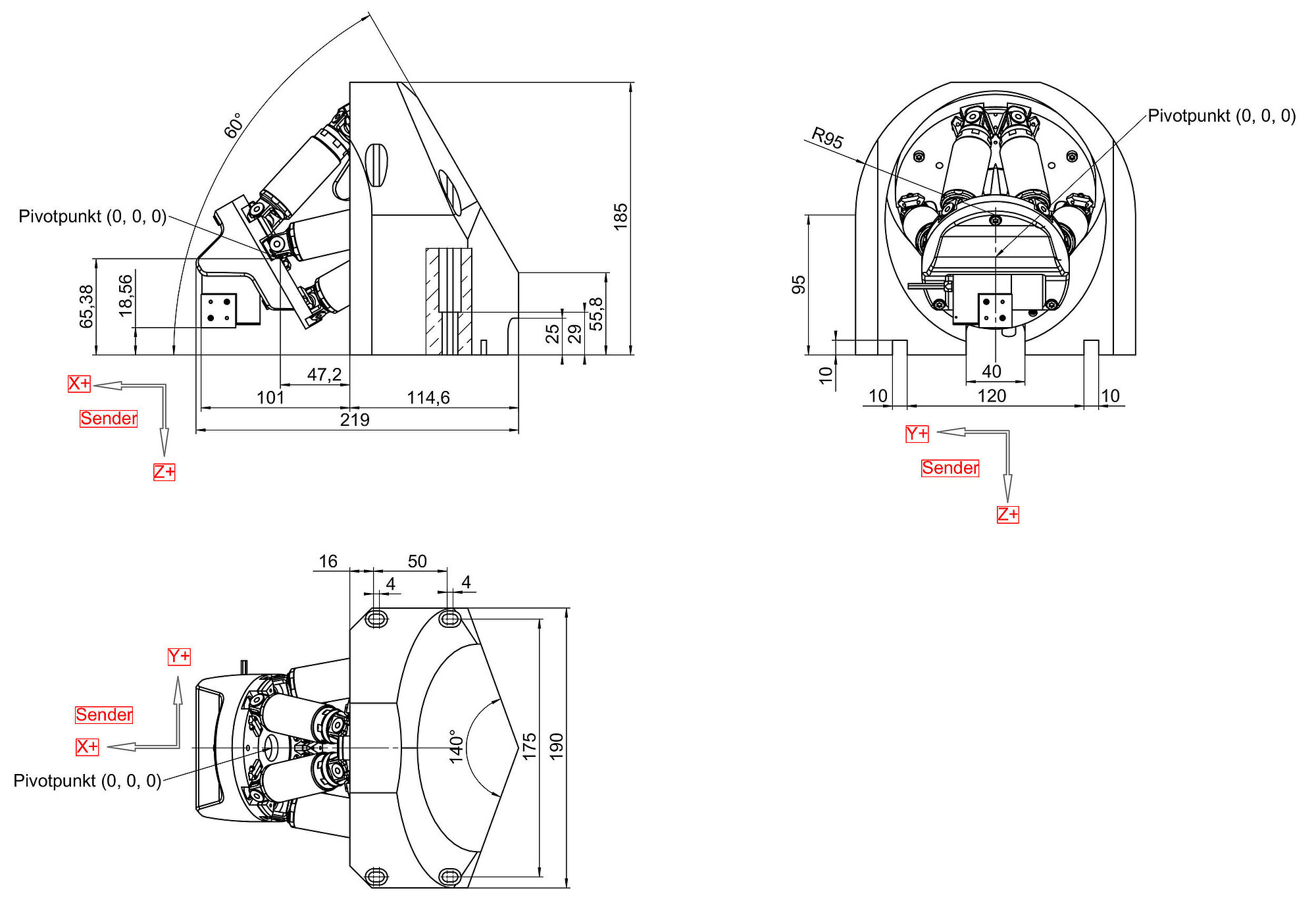
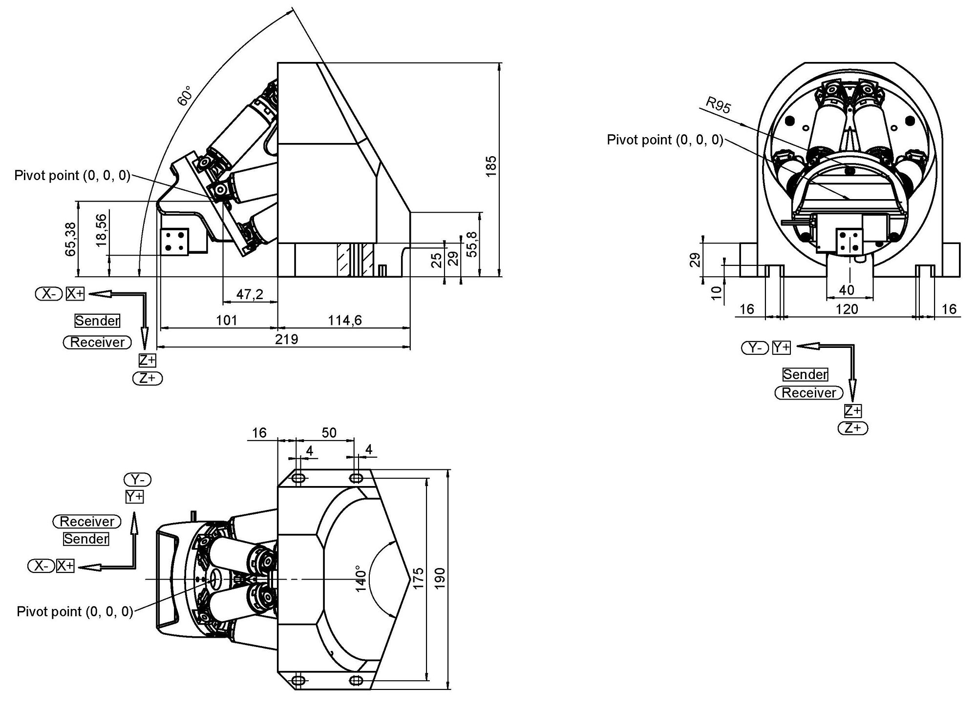
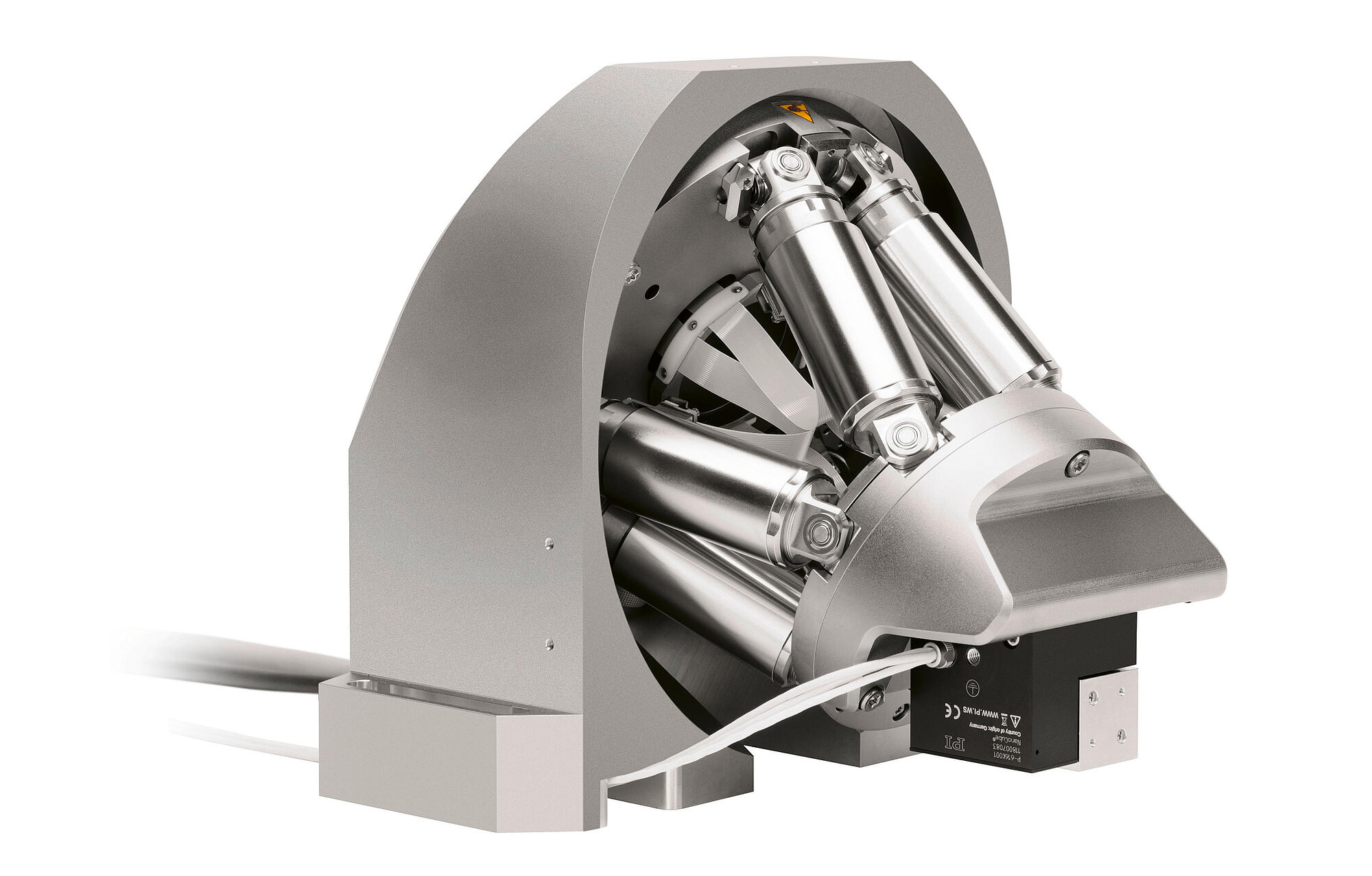
The F-713.HA1 and F-713.HA2 single-sided and double-sided angled configurations offer a low profile. This means that the alignment can be performed close to (or even under) the mounting surface thanks to the hexapod’s angled mounting. Ideal for silicon photonics wafer probing applications.
The F-713.HU1 single-sided upright configuration is ideal for device characterization and packaging processes. Upright configurations for two or even more sides are available on request.
Starting with these sophisticated platforms, it is easy to configure further alignment solutions of unprecedented speed that support functionalities such as submicron-sensitive wafer proximity automation.
Application fields
PIC production, alignment of fiber arrays, collimators, optical components or lenses, silicon photonics wafer probing, testing, assembly, and packaging of photonics and fiber optics
Specifications
Specifications
Motion and positioning | F-713.HA1 | F-713.HA2 | F-713.HU1 | Tolerance |
---|---|---|---|---|
Number of active axes | 9 | 18 | 9 | |
Active axes, rough positioning | X ǀ Y ǀ Z ǀ θX ǀ θY ǀ θZ | X ǀ Y ǀ Z ǀ θX ǀ θY ǀ θZ | X ǀ Y ǀ Z ǀ θX ǀ θY ǀ θZ | |
Travel range in X, rough positioning | 13 mm | 13 mm | 34 mm | |
Travel range in Y, rough positioning | 32 mm | 32 mm | 32 mm | |
Travel range in Z, rough positioning | 17 mm | 17 mm | 13 mm | |
Minimum incremental motion in X, rough positioning | 0.1 µm | 0.1 µm | 0.1 µm | |
Minimum incremental motion in Y, rough positioning | 0.1 µm | 0.1 µm | 0.1 µm | |
Minimum incremental motion in Z, rough positioning | 0.1 µm | 0.1 µm | 0.05 µm | |
Maximum velocity in X, rough positioning, unloaded | 10 mm/s | 10 mm/s | 10 mm/s | |
Maximum velocity in Y, rough positioning, unloaded | 10 mm/s | 10 mm/s | 10 mm/s | |
Maximum velocity in Z, rough positioning, unloaded | 10 mm/s | 10 mm/s | 10 mm/s | |
Rotation range in θX, rough positioning | 29 ° | 29 ° | 20 ° | |
Rotation range in θY, rough positioning | 20 ° | 20 ° | 20 ° | |
Rotation range in θZ, rough positioning | 20 ° | 20 ° | 42 ° | |
Drive type, rough positioning | Brushless DC motor | Brushless DC motor | Brushless DC motor | |
Sensor type, rough positioning | Rotary encoder | Rotary encoder | Rotary encoder | |
Active axes, fine positioning | X ǀ Y ǀ Z | X ǀ Y ǀ Z | X ǀ Y ǀ Z | |
Travel range in X, fine positioning | 100 µm | 100 µm | 100 µm | |
Travel range in Y, fine positioning | 100 µm | 100 µm | 100 µm | |
Travel range in Z, fine positioning | 100 µm | 100 µm | 100 µm | |
Minimum incremental motion in X, open-loop, fine positioning | 0.3 nm | 0.3 nm | 0.3 nm | |
Minimum incremental motion in Y, open-loop, fine positioning | 0.3 nm | 0.3 nm | 0.3 nm | |
Minimum incremental motion in Z, open-loop, fine positioning | 0.3 nm | 0.3 nm | 0.3 nm | |
Minimum incremental motion in X, closed-loop, fine positioning | 2.5 nm | 2.5 nm | 2.5 nm | |
Minimum incremental motion in Y, closed-loop, fine positioning | 2.5 nm | 2.5 nm | 2.5 nm | |
Minimum incremental motion in Z, closed-loop, fine positioning | 2.5 nm | 2.5 nm | 2.5 nm | |
Linearity error in the nominal measuring range | 2 % | — | — | max. |
Bidirectional repeatability in X, 10 % travel range | 2 nm | 2 nm | 2 nm | typ. |
Bidirectional repeatability in Y, 10 % travel range | 2 nm | 2 nm | 2 nm | typ. |
Bidirectional repeatability in Z, 10 % travel range | 2 nm | 2 nm | 2 nm | typ. |
Drive type, fine positioning | PICMA® | PICMA® | PICMA® | |
Sensor type fine positioning | Incremental linear encoder | Incremental linear encoder | Incremental linear encoder | |
Adjustment | F-713.HA1 | F-713.HA2 | F-713.HU1 | Tolerance |
Scanning time of spiraled area scan 10 µm Ø | < 0.2 s | < 0.5 s | < 0.2 s | typ. |
Scanning time of spiraled area scan 100 µm Ø | < 0.3 s | < 1 s | < 0.3 s | typ. |
Scanning time of spiraled area scan 500 µm Ø | < 2 s | < 5 s | < 2 s | typ. |
Signal optimization with gradient search, randomized with ±5 μm (repeatability < 0.01 dB) | 0.3 s | 0.3 s | 0.3 s | |
Requirements for the optical power meter | F-713.HA1 | F-713.HA2 | F-713.HU1 | Tolerance |
Output signal | Analog output, ideally converted from linear to logarithmic | Analog output, ideally converted from linear to logarithmic | Analog output, ideally converted from linear to logarithmic | |
Maximum output voltage range | -5 to 5 V | -5 to 5 V | -5 to 5 V | max. |
Minimum bandwidth | 1 kHz | 1 kHz | 1 kHz | min. |
Maximum noise level | -60 dBm | -60 dBm | -60 dBm | max. |
Note on linearity error: no polynomial linearization
Scanning time: typical time span for scanning the entire area and moving to the highest intensity
Signal optimization with gradient search: reaching the global maximum after first light has been found
Note on operating temperature range: specification applies to mechanics; operating temperature range for controller: 5°C to 40°C
Ask about customized versions
When measuring position specifications, typical velocity is used. The data is included in the delivery of the product in the form of a measurement report and is stored at PI.
The maximum travel ranges of the individual coordinates (X, Y, Z, θX, θY, θZ) are interdependent. The data for each axis shows its maximum travel range when all other axes are in the zero position of the nominal travel range and the default coordinate system is in use, or rather when the pivot point is set to 0,0,0.
See the dimensional drawings for the default coordinate system and pivot point coordinates of the hexapod. Changing the pivot point will reduce the travel range in θX, θY, θZ. Changing the orientation of the coordinate system (e.g., when the optical axis is to be the Z axis) will change the travel range in X, Y, and Z.
When measuring position specifications, typical velocity is used. The data is included in the delivery of the product in the form of a measurement report and is stored at PI.
The maximum travel ranges of the individual coordinates (X, Y, Z, θX, θY, θZ) are interdependent. The data for each axis shows its maximum travel range when all other axes are in the zero position of the nominal travel range and the default coordinate system is in use, or rather when the pivot point is set to 0,0,0.
At PI, technical data is specified at 22 ±3 °C. Unless otherwise stated, the values are for unloaded conditions. Some properties are interdependent. The designation "typ." indicates a statistical average for a property; it does not indicate a guaranteed value for every product supplied. During the final inspection of a product, only selected properties are analyzed, not all. Please note that some product characteristics may deteriorate with increasing operating time.
Ask for a free quote on quantities required, prices, and lead times or describe your desired modification.
Double-sided photonics alignment system consisting of 2 H-811 hexapods and 2 NanoCube® nanopositioners; E-713 digital controller with 4 analog inputs; 2 C-887 hexapod controllers each with 2 analog inputs; firmware routines for high-speed alignment tasks; software package
Single-sided photonics alignment system consisting of H-811 hexapod and NanoCube® nanopositioner, upright configuration; E-713 digital controller with 4 analog inputs; C-887 hexapod controller with 2 analog inputs; firmware routines for high-speed alignment tasks; software package
견적 요청 방법
Ask an engineer!
Quickly receive an answer to your question by email or phone from a local PI sales engineer.
기술

Active Alignment
The need to align devices down to nanoscale accuracy is arising in many fields. Optical components such as the lenses or lens assemblies in small cameras, or even the CCD chip itself, need to be positioned with ever more precision.

Hexapods and SpaceFAB
Hexapods are systems for moving and positioning loads in six degrees of freedom, in three translational and three rotational axes.